NSN 3040-01-171-9539
Part Details | STRAIGHT SHAFT
3040-01-171-9539 A straight shaft having two or more of the following conditions: a specified surface finish designation in the range of 1 to 125 microinches (o.o25 to 3.2 micrometers), arithmetical average (aa), machined peripheral flat(s), circular groove (s), keyway(s), splines, threads, or holes. It is not designed for use in aligning by fitting into corresponding holes of another item. It may be drilled for lubricating holes. For items having an integral gear(s) or worm(s), see GEARSHAFT (as modified). For items designed to support rotating members see AXLE(1), STRAIGHT. For items not having the above conditions see PIN, STRAIGHT, HEADLESS. For items having machined ends which constitute steps see SHAFT(1), SHOULDERED; AXLE(1), SHOULDERED; and BOLT, FLUID PASSAGE.
Alternate Parts: 1107165, 1107-165, 3040-01-171-9539, 01-171-9539, 3040011719539, 011719539
| Supply Group (FSG) | NSN Assigned | NIIN | Item Name Code (INC) |
|---|---|---|---|
| 30 | FEB 15, 1984 | 01-171-9539 | 22109 ( SHAFT, STRAIGHT ) |
REFERENCE DRAWINGS & PICTURES
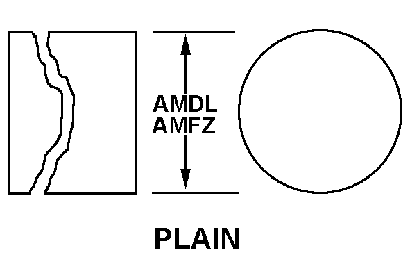
PLAIN
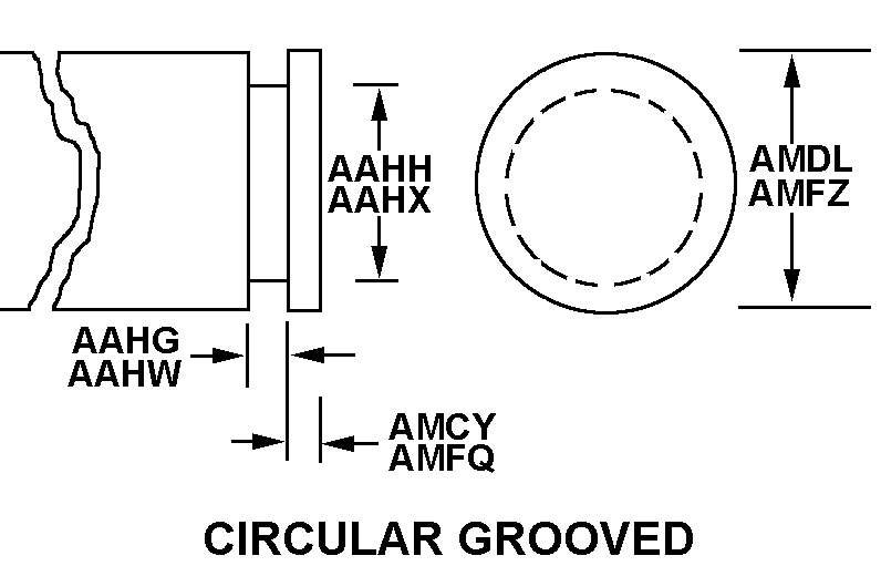
CIRCULAR GROOVED
PLAIN
CIRCULAR GROOVED
Cross Reference | NSN 3040-01-171-9539
| Part Number | Cage Code | Manufacturer |
|---|---|---|
| 1107-165 | 72314 | BAE SYSTEMS INFORMATION ANDELECTRONIC SYSTEMS INTEGRATION I |
Technical Data | NSN 3040-01-171-9539
| Characteristic | Specifications |
|---|---|
| MATERIAL | STEEL COMP 303 |
| MATERIAL DOCUMENT AND CLASSIFICATION | QQ-S-764 COND A COLD FINISH FED SPEC SINGLE MATERIAL RESPONSE |
| FIRST END STYLE | CIRCULAR GROOVED |
| FIRST END GROOVE WIDTH | 0.0300 INCHES NOMINAL |
| FIRST END GROOVE DIAMETER | 0.2080 INCHES MINIMUM AND 0.2120 INCHES MAXIMUM |
| FIRST END DISTANCE FROM END TO GROOVE | 0.045 INCHES NOMINAL |
| FIRST END DIAMETER | 0.2493 INCHES MINIMUM AND 0.2497 INCHES MAXIMUM |
| END SIMILARITY | NOT IDENTICAL |
| SECOND END STYLE | 2 PLAIN |
| SECOND END DIAMETER | 0.2493 INCHES MINIMUM AND 0.2497 INCHES MAXIMUM |
| SECOND END EXTERNAL THREAD LENGTH | 0.112 INCHES NOMINAL |
| OVERALL LENGTH | 2.500 INCHES NOMINAL |