NSN 4710-01-196-4145
Part Details | METALLIC TUBE
4710-01-196-4145 A straight, hollow product, welded or seamless, of round, square, or any other cross section and continuous periphery, which does not conform in cross sectional dimensions to recognized pipe standards, or those in Tables 1 through 10, Appendix C, FIIG A004A. It is designed to convey fluids, gasses, and/or semisolids. It may be rolled into coils for ease in handling. For items designed to join a tube or tube fitting to another tube, pipe, or hose or fitting, see ADAPTER (as modified); COUPLING (as modified); or NIPPLE (as modified). Excludes TUBE, BENT (as modified); PIPE, METALLIC; SPACER, SLEEVE; METAL BAR (hollow); and items with fittings, except end protectors.
Alternate Parts: CW2300AN PIECE 390, CW-2300AN PIECE 390, CW2300AN PIECE 390, CW-2300AN PIECE 390, CW2300AN, CW-2300AN, 4710-01-196-4145, 01-196-4145, 4710011964145, 011964145
| Supply Group (FSG) | NSN Assigned | NIIN | Item Name Code (INC) |
|---|---|---|---|
| 47 | DEC 11, 1984 | 01-196-4145 | 31979 ( TUBE, METALLIC ) |
REFERENCE DRAWINGS & PICTURES
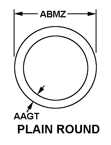
PLAIN ROUND
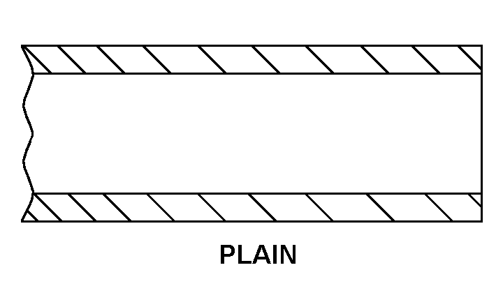
PLAIN
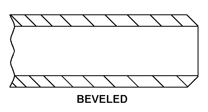
BEVELED
PLAIN
BEVELED
Cross Reference | NSN 4710-01-196-4145
| Part Number | Cage Code | Manufacturer |
|---|---|---|
| CW-2300AN PIECE 390 | 65427 | D.C. FABRICATORS INC. |
| CW-2300AN PIECE 390 | 16712 | SIEMENS DEMAG DELAVALTURBOMACHINERY, INC. |
| CW-2300AN | 16712 | SIEMENS DEMAG DELAVALTURBOMACHINERY, INC. |
Technical Data | NSN 4710-01-196-4145
| Characteristic | Specifications |
|---|---|
| MATERIAL | COPPER ALLOY |
| MATERIAL DOCUMENT AND CLASSIFICATION | MIL-T-15005, COMP 70-30 MIL SPEC SINGLE MATERIAL RESPONSE |
| MEASURING METHOD AND LENGTH | S+265.250 INCHES NOMINAL |
| CROSS-SECTIONAL SHAPE STYLE | PLAIN ROUND |
| WALL THICKNESS | 0.060 INCHES NOMINAL |
| DIAMETER | 0.625 INCHES NOMINAL |
| FIRST END STYLE | PLAIN |
| FIRST END OUTSIDE DIAMETER | 0.750 INCHES NOMINAL |
| SECOND END RELATIONSHIP WITH FIRST END | NOT IDENTICAL |
| SECOND END STYLE | BEVELED |
| CONSTRUCTION | SEAMLESS |
| SPECIAL FEATURES | TWO SETS OF 3 GROOVES EACH PER EACH END; 0.062 INCH WIDE BY 0.012 INCH DEEP;SPACED 0.094 INCH BETWEEN EACH GROOVE; ONE SET OF GROOVES TO END 1.000 INCH FROM TUBE END AND SECOND SET OF GROOVES TO BEGIN 3.500 INCHES FROM END OF FIRST SET OF GROOVES |