NSN 5365-01-173-8559
Part Details | PLATE SPACER
5365-01-173-8559 A flat metal or plastic item of various peripheral shapes having a solid (not laminated) cross-section. It is designed to maintain a predetermined distance between two surfaces. For round items without a hole having a solid rectangular cross-section use DISK, SOLID, PLAIN. For round or hexagonal items with only one hole centrally located and with the length (thickness) exceeding 25 percent of the outside diameter or distance across peripheral flats, see SPACER, SLEEVE. The thickness between the two parallel bearing surfaces must be 0.006 inch, (0.152 mm) or more for items less than 1/4 inch (6.35 mm) across the peripheral diameter, or smallest overall outside dimension, or must be 0.016 inch (0.406 mm) or more for items 1/4 inch (6.35 mm) or greater across the peripheral diameter or smallest overall outside dimension. For items with a thickness less than those indicated above, see SHIM. For items with one hole centrally located conforming to the above dimensional criteria use WASHER, FLAT or SPACER, RING as applicable. When thickness and/or outside diameter or smallest overall outside dimension is designated as a tolerance/dimension the maximum dimension will be used to determine compliance. Excludes GASKET; INSULATOR (as modified) and MOUNTING PAD, ELECTRICAL-ELECTRONIC COMPONENT.
Alternate Parts: 9528M95P01, 9528M95P01, 5365-01-173-8559, 01-173-8559, 5365011738559, 011738559
| Supply Group (FSG) | NSN Assigned | NIIN | Item Name Code (INC) |
|---|---|---|---|
| 53 | MAR 10, 1984 | 01-173-8559 | 26979 ( SPACER, PLATE ) |
REFERENCE DRAWINGS & PICTURES
CIRCULAR
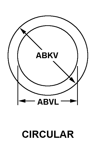
Cross Reference | NSN 5365-01-173-8559
| Part Number | Cage Code | Manufacturer |
|---|---|---|
| 9528M95P01 | 07482 | GENERAL ELECTRIC COMPANYDBA GE |
| 9528M95P01 | 03350 | GENERAL ELECTRIC COMPANYDBA GE STRUCTURED SERVICES DIV |
Technical Data | NSN 5365-01-173-8559
| Characteristic | Specifications |
|---|---|
| MATERIAL | NICKEL ALLOY 625 |
| MATERIAL DOCUMENT AND CLASSIFICATION | AMS 5599 ASSN STD SINGLE MATERIAL RESPONSE |
| BOLT HOLE QUANTITY | 2 |
| STYLE DESIGNATOR | 6A CIRCULAR |
| HOLE DIAMETER | 0.294 INCHES MINIMUM AND 0.303 INCHES MAXIMUM |
| OVERALL LENGTH | 1.610 INCHES MINIMUM AND 1.650 INCHES MAXIMUM |
| OVERALL WIDTH | 0.620 INCHES MINIMUM AND 0.660 INCHES MAXIMUM |
| CENTER TO CENTER DISTANCE BETWEEN BOLT HOLES ALONG LENGTH | 0.850 INCHES MINIMUM AND 0.870 INCHES MAXIMUM |
| OUTSIDE EDGE TO BOLT HOLE CENTER DISTANCE ALONG LENGTH | 0.390 INCHES MINIMUM AND 0.410 INCHES MAXIMUM |
| BOLT HOLE CENTERLINE TO NEAREST EDGE DISTANCE | 0.250 INCHES MINIMUM AND 0.270 INCHES MAXIMUM |
| SPECIAL FEATURES | 2 CORNERS ALONG LG CHAMFERED 0.200-0.230 IN. BY 45.0 DEG |
| END ITEM IDENTIFICATION | F-101 ENGINE,B-1B ACFT |