NSN 5930-00-168-7969
Part Details | PUSH SWITCH
5930-00-168-7969 A switch that is externally actuated by a device such as a push rod or button, which requires pushing for each actuation. The action may be momentary, with mechanical return. The actuating device may or may not be an integral part of the switch. The item may include provisions for mounting indicating lamp(s) or light emitting diode(s) in the actuator. Includes items consisting of individually separable switches that are physically interlocked, that have a common actuator, or are electrically connected. Excludes LIGHT-SWITCH; LIGHT-SWITCH ASSEMBLY; SWITCH, BEAM SELECTING, HEADLIGHT; SWITCH, FOOT; SWITCH, INTERLOCK; SWITCH, PRESSURE; SWITCH, PUSH-PULL; SWITCH, SENSITIVE and SWITCH ASSEMBLY. For devices which start, stop, reverse, select and/or regulate the speed of a motor, see STARTER, MOTOR and CONTROLLER, MOTOR.
Alternate Parts: 20102510, 201025-10, 5930-00-168-7969, 00-168-7969, 5930001687969, 001687969
| Supply Group (FSG) | NSN Assigned | NIIN | Item Name Code (INC) |
|---|---|---|---|
| 59 | OCT 19, 1970 | 00-168-7969 | 00406 ( SWITCH, PUSH ) |
REFERENCE DRAWINGS & PICTURES
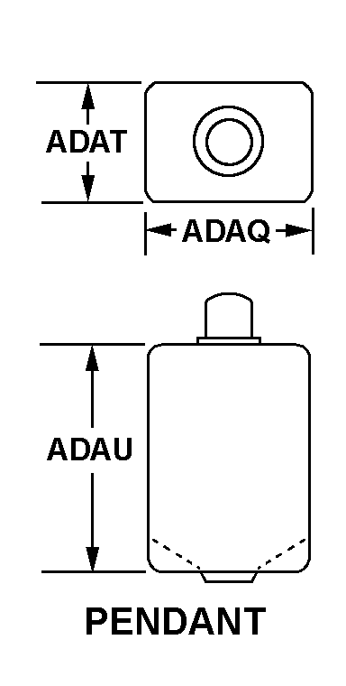
PENDANT
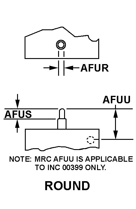
ROUND
Cross Reference | NSN 5930-00-168-7969
| Part Number | Cage Code | Manufacturer |
|---|---|---|
| 201025-10 | 12522 | STACO SYSTEMS, INC.DBA STACO SWITCH |
Technical Data | NSN 5930-00-168-7969
| Characteristic | Specifications |
|---|---|
| MAXIMUM VOLTAGE RATING IN VOLTS | 115.0 AC AND 28.0 DC |
| CONTACT LOAD CURRENT RATING AT MAXIMUM RATED VOLTAGE | C2.000 AMPERES RESISTIVE AND B1.500 AMPERES RESISTIVE |
| BODY STYLE | PENDANT |
| BODY LENGTH | 0.750 INCHES MAXIMUM |
| BODY WIDTH | 0.750 INCHES MAXIMUM |
| OVERALL LENGTH | 0.870 INCHES MAXIMUM |
| OVERALL WIDTH | 0.870 INCHES MAXIMUM |
| OVERALL HEIGHT | 3.050 INCHES MAXIMUM |
| ACTUATOR STYLE | 3 ROUND |
| ACTUATOR LENGTH | 0.680 INCHES NOMINAL |
| ACTUATOR HEIGHT | 0.300 INCHES NOMINAL |
| ACTUATOR WIDTH | 0.680 INCHES NOMINAL |
| TERMINAL TYPE AND QUANTITY | 16 TAB, SOLDER LUG |
| INCLOSURE TYPE | FULLY INCLOSED |
| MOUNTING METHOD | INTEGRAL |
| ILLUMINATED ACTUATOR COLOR SEQUENCE | UPPER LEFT HALF OF ACTUATOR RED UPPER RIGHT HALF OF ACTUATOR YELLOW LOWER HALF OF ACTUATOR GREEN |